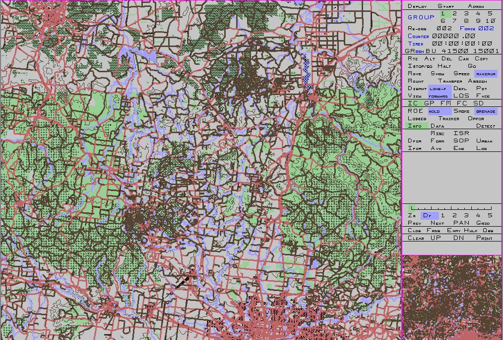
One of the simplest ways to describe the differences between the Australian (AS) version and the many other versions of Janus is to review the graphical user interface (GUI). Those familiar with another version will recognise the basic display, but will immediately notice a number of differences.
Terminology: Interactor is the name given to the person who operates the computer display/ workstation. Icon refers to one of the combat entities under control of a given interactor. Force refers to the complete set of entities under control of one interactor.
The Janus (AS) has 4 modes of operation: Deploy mode refers to the initial phase where the simulation is not actually running and interactors are able to position their icons and issue initial orders. Battle mode refers to the phase where the simulation is running, icons are moving and shooting etc according to their orders. Pause mode occurs during battle mode when the simulation clock is temporarily paused and simulation events consequently stop being processed, but interactors are still able to issue orders. Admin mode also pauses the simulation, but interactors are unable to continue issueing orders. instead, the simulation controller can perform a variety of administative tasks.
The first thing to note is that the AS version uses a white background for the map display. This was found to make switching between printed paper maps and the computer display easier. Underlying Janus is a 3 dimensional terrain model. Features such as woods, water and roads are displayed in relatively obvious colours.

The display is divided into 3 main areas: the large scalable map, the reference map and the menu. All orders that can be issued to icons are available through the menu. The Janus menu functions like a tool bar in common graphics programs. The function, such as 'move' is first selected and then that order is issued to icons by clicking on them with the mouse. For some functions, variations on the orders can be issued using different mouse buttons.
The words on the menu in black text are buttons or functions that can be selected. The words in blue text (or red) are labels and can not be selected. The areas with a green background denote that a particular function has been selected. The areas with a blue background denote that a button is not a function but a changeable parameter for another function. Clicking on such a location changes the value of the parameter. This provides a surrogate for the drop down pick list windows widget.
The menu is divided into a number of regions. The very top row of buttons relate mainly to admin fuctions. The deploy button is used to deploy or position icons during the deploy mode. The start button is used to end deploy mode and signify that workstation is ready to change to battle mode. The admin button is used to pause the simulation and enter Admin mode.
The next section contains global values such as the counter and timer. These are used by many other functions to specify how certain things will operate. For example, many orders can be issued to a whole group not just a single icon. The numbers 1 to 10 are used to select which of the 10 groups will receive the order. The reorg function is used to move icons from one group to another or to send them to a different force. On the controller workstation, icons can also be grabbed from another force.

The next section has all the most common orders and functions. Icons can be ordered to move, mount, transfer passengers, dismount and so on. A few of these functions are different to other versions.
Speed is used to set the speed of an icon. This allows icons to travel at speeds slower than their maximum. For example, vehicles can be slowed to match the speed of accompanying infantry, or vehicles in a formation can be slowed to maintain the formation. The speed is set using the counter described in the previous section.
The view function is used to set the direction of view for an icon. By default, this is straight ahead (ie the direction of movement or facing). However it can also be set to an offset, so that icons in a formation can cover different arcs. It can also be set to a fixed point so that no matter which way an icon moves, it will continue to view the same point of the ground. This is a useful function for aircraft tasked with observing a specific area.
The face function is used to change the direction an icon is facing. This can be used to ensure an icon keeps its frontal armour pointed in the direction of the enemy.
The RTE function is the same as other versions in that it allows movement routes to be created using ‘nodes’ or way points. The difference in the AS version is that these nodes can also be ‘activity nodes’. That is, as well as marking a way point, an icon can be ordered to take an action at that point, such as change speed, change altitude, dismount passengers, change primary sensor, set a trigger point and so on. Most of the orders that can be given to an icon can also be given to an activity node. In this way, quite complex plans can be pre-programmed.
There is also a special dismount mode for aircraft to represent parachuting. Icons dismounted from an aircraft scatter along the aircraft's fligh path according to the aircraft speed, altitude and wind direction.

The scope section is used to define the scope of an order. As well as giving an order to the selected icon (IC), orders can be given to a whole group (As noted above, icons must be grouped into one of ten groups), a formation (see below), the force, or to a side (which is only used for report functions).

The next section is largely devoted to reports. Losses, info and data all produce text reports. Tracker and Opfor produce graphical reports (if enabled for the force) that show where friendly forces are (tracker) or where friendly forces have detected enemy forces (Opfor). Detect is used to graphically display which icons can detect which enemy icons. On a control workstation, this can also be used to show which icons have been detected.
The ROE function changes the ‘rules of engagement’. That is, the circumstances under which icons will engage other icons. The options are: hold (never shoot at anything), tight (may engage any positively identified enemy) and free (may engage anything not positively identified as friendly. Optional additional modes can be activated when the scenario is created that add: very tight (only enemy who are also shooting), loose (anyone shooting at this force), very loose (anyone aiming at this force) and down (do not even aim at other icons).
A note about ‘aiming’ is necessary here. By default, even an icon on ‘weapons hold’ will aim at other icons. This allows icons to be aiming in anticipation of an icon change observed state (from unknown to enemy for example) or of a command fire order (see below).
This raises the point about observation states. A foreign icon (ie not belonging to this force) can be in one of four observation states: not observed (in which case it is not displayed), detected (in which case it is displayed as a yellow letter: I for infantry, W for wheeeled vehicle, F for flyer etc denoting that the entity has been glimpsed but not identified), recognised (a yellow icon denoting the type of platform is known but not whether it is enemy of friendly) and identified (a blue, red or purple icon denoting that it is known to be friendly, enemy or neutral).

One of the major changes was an attempt to create more 'real estate' for the menu. To achieve this, an area has been created that works similarly to a tab widget in a windows display. Each of the headings causes a different submenu to be displayed in the clear area below.

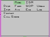
The ‘MISC’ section is used for functions that had no better place to go. Contact turns on and off contact reporting (new detection events) and call signs turns on and off the display of icon call signs.
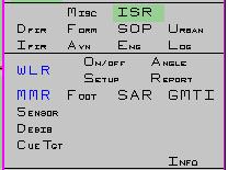
ISR is used for all of the advanced functions relating to sensors and observation. It includes controls for weapon locating radar, airborne multi-mode radar, and laser designators.
It also includes a function for ordering an icon to cue onto a target already detected by another icon in the force. This is an artefact of the way the detection model works. It is possible that one icon will detect a target, while another on the same force does not due to the way targets are sorted (for speed efficiency). The cue function puts the cued target icon on the top of the observer’s search list which means as long as it is possible to detect it (ie line of sight is not blocked) it should do so quite quickly.
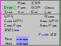
The DFIR section relates to direct combat. This includes: the command fire function that allows the interactor to override the automatic target selection and nominate a specific target; the area fire fiction that allows direct fire weapons to target areas rather than specific icons, and the rate of fire and area used when using area fire It also includes the ‘range’ feature that allows the interactor to limit the area that an icon will engage. That is, by default, an icon will engage targets (depending on the current ROE) out to the maximum weapon range. The range function can be used to reduce this range so that only targets within a certain range will be engaged, or to apply a minimum range where only targets beyond that range will be engaged or to restrict the arc or field of fire in which targets will be engaged.
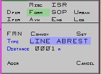
The FORM menu is used to manage formations. This is a special grouping of icons that attempt to maintain a geometric formation when they move. The possible formations include: line abreast, single file, wedge, left and right echelon, left and right box and many others. One icon in the formation is designated as the leader. This becomes the reference point for the formation and it is orientated about the leader’s direction of facing (movement). It is also possible to create any geometric pattern by simply moving the icons into a formation and then creating the formation based on that arrangement.
Formations can be nested so that a follower in one formation can be a leader in another formation.
A convoy is a special type of formation. Icons in convoy do not attempt to maintain a geometric formation. Instead, they attempt to remain a set distance from the convoy leader. in this way, they can be moved along a road and as soon as the leader stops, all of the followers in the convoy will stop maintaining their set spacing.
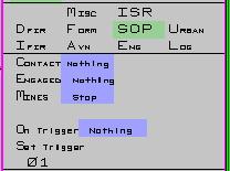
The SOP menu controls some automated behaviours. These are such things as responding to a new contact (stop); responding to being engaged by direct fire (stop, turn to face, pop smoke), or responding to encountering a mine (stop, start clearing).
The trigger functions are a way to synchronise the activity of a number of icons. Normally, a trigger (numbered from 1 to 99) is assigned to an activity node for an icon. When that icon reaches that node, it ‘triggers’ the correspondingly numbered command. Any other icons in the same force that have been set to respond to that trigger will do so. Examples include: stop, go, check fire, resume fire, and end mission. Internally, any command that may be issued by an interactor can be set as a trigger response, but this more advanced feature can only be accessed using the Janus(AS) scripting language.
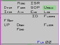
The URBAN menu controls functions relating to urban operations such as: occupying a firing port in a building and moving up and down floors.
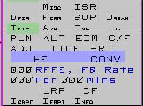
The IFIR section controls indirect fire functionality. Janus(AS) uses two part fire missions with a fire for effect (as fast as possible) initial component and then a sustained fire rate over time. Either or both parts can be assigned to a mission. Missions can also be ‘checked’ (ie paused) as well as ended and repeated. Laser designated and terminally guided rounds are also supported.
Aggregated missions can also be created in which case, the guns will synchronise their fire so that the first round of each mission hits the target at approximately the same time.
Registration missions can also be fired which create registration zones that improve accuracy, or laser registration points can be created to represent more advanced range finding.
The AVN menu has the controls specific to aircraft including setting altitude (above mean sea level or above ground level), creating a release point activity node (where bombs will be dropped) and setting the aircraft in a holding circle.
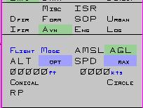
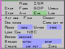
The ENG menu controls combat engineering functions such as mine clearing and bridge laying. It is also used to set the behaviour of icons when they encounter obstacles. For example, when an icon encounters a water obstacle, it may ford, swim, use a bridge (if available) or stop depending on this setting.
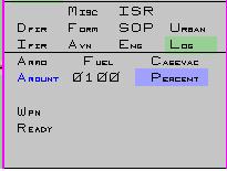
The LOG menu is used to control resupply functions Fuel and ammunition are consumed during the simulation and specific icons can be included that carry additional supplies that can be uploaded during the scenario. The amount of supplies transferred can be controlled by percentage or absolute amount.
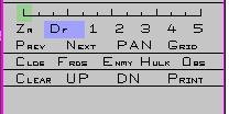
The final section is largely devoted to navigation. It includes the zoom function along with panning and the ability to save particular views and quickly return to them. The zoom function is also able to use the grid counter from the top section of the menu or to zoom to a specific icon (by number) of the last ‘alert’ message. Alert messages include events such as receiving direct fire or a new detection event.
Additionally, this section is used to clear some of the graphics, such as removing the display of friendly icons or obstacles. this helps to de-clutter the display when it is particularly busy.
More detailed information on the functionality of Janus(AS) can be found in the material used to train interactors.